|
|
|
Categories
|
|
Information
|
|
Featured Product
|
|
|
 |
|
|
There are currently no product reviews.
 ;
This is a good quality scan of the Operation & Maintenance (Service) Manual for the PAL version of this high-band broadcast umatic, BVU-800P
All schematics and lineup procedures appear to be included in this one manual AFAICT.
The file size is just over 113 MB which gives an idea of the quality and number of pages.
All of the schematics, which contain some fairly small print, are easily readable when you zoom into the page.
John Thompson, Newcastle Upon Tyne, England.
;
Good quality, all schematics of few of models. There is also short form of user manual and regulation manual.
;
Perfect copy of the service manual. you can enlarge every page, and it comes up
with all details.
;
It´s very very nice manual with all, what i need. Original in good quality. Very fast business. Very much thanks...
;
Purchased the manual that I was looking for at a great price and could download it easily.. Great service experience and for future purchases I plan to use the site.
Thank you very much
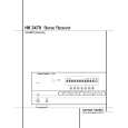
HK3370/HK3470
<8> PHONES P. C. BOARD(e) REMOVAL. 1. Remove the Chassis-top(44), referring to the previous step<1>. 2. Remove the Front-panel ASS'Y(AA), referring to the previous step<2>. 3. Disconnect the lead wire(CW 801, 3P) from connector(CN 401) on the Amp P. C. Board(h). 4. Remove 2 screws(E) and then remove the Phones P. C. Board(e). <9> POWER P. C. BOARD(f) REMOVAL. 1. Remove the Chassis-top(44), referring to the previous step<1>. 2. Remove the Front-panel ASS'Y(AA), referring to the previous step<2>. 3. Disconnect the lead wire(CW 801, 5P) from connector(CN 302) on the Front P. C. Board(d). 4. Remove 2 screws(J) and then remove the Power P. C. Board(f). <10> STANDBY P. C. BOARD(g) REMOVAL. 1. Remove the Chassis-top(44), referring to the previous step<1>. 2. Remove the Front-panel ASS'Y(AA), referring to the previous step<2>. 3. Remove 2 screws(J) and then remove the Standby P. C. Board(g). <11> TUNER P. C. BOARD(j) REMOVAL. 1. Remove the Chassis-top(44), referring to the previous step<1>. 2. Remove 21 screws(G,K) and then remove the Chassis-back(41). 3. Pull out the Tuner P. C. Board(j). <12> RADIATOR ASS'Y(AB) REMOVAL. 1. Remove the Chassis-top(44), referring to the previous step<1>. 2. Disconnect the connector(CN 401) from lead wire(CW 801, 3P) on the Phones P. C. Board(e). 3. Disconnect the lead wire(CW 403, 4P) from connector(CN 111, CN 112) on the Main P. C. Board(i). 4. Disconnect the lead wire(CW 402, 10P) from connector(CN 107) on the Main P. C. Board(i). 5. Disconnect the lead wire(CW 401, 4P) from connector(CN 108) on the Main P. C. Board(i). 6. Remove 7 screws(I) and then pull out the Radiator Ass'Y(AB). <13> AMP P. C. BOARD(h) REMOVAL. 1. Remove the Chassis-top(44), referring th the previous step<1>. 2. Remove the Radiator Ass'Y(AB), referring to the Previous step<12>. 3. Disconnect the connector(CN 402) from lead wire(posistor, 2P) on the Radiator-main (21). 4. Remove 4 screws(D) and then remove the Amp P. C. Board(h). <14> POWER TRANS(38) REMOVAL. 1. Remove the Chassis-top(44), referring to the previous step<1>. 2. Disconnect the lead wire(2P) from connector(CN 103) on the Main P. C. Board(i). 3. Disconnect the lead wire(3P) from connector(CN 104) on the Main P. C. Board(i). 4. Disconnect the lead wire(6P) from connector(CN 105) on the Main P. C. Board(i). 5. Disconnect the lead wire(3P) from connector(CN 106) on the Main P. C. Board(i). 6. Remove 4 screws(B) and then remove the Power trans(38). <15> MAIN P. C. BOARD(i) REMOVAL. 1. Remove the Chassis-top(44), referring to the previous step<1>. 2. Remove the Tuner P. C. Board(j), referring to the previous step<11>. 3. Disconnect the connector(CN 109) from lead wire(CW 701, 10P) on the Volume P. C. Board(b). 4. Disconnect the connector(CN 108) from lead wire(CW 401, 4P) on the Amp P. C. Board(h). 5. Disconnect the connector(CN 115) from connector(CN 301, card cable) on the Front P. C. Board(d). 6. Disconnect the connector(CN 107) from lead wire(CW 402, 10P) on the Amp P. C. Board(h). 7. Disconnect the connector(CN 106) from lead wire(3P) on the Power-trans(38). 8. Disconnect the connector(CN 105) from lead wire(6P) on the Power-trans(38). 9. Disconnect the connector(CN 113) from lead wire(CW 301, 7P) on the Front P. C. Board(d). 10. Disconnect the connector(CN 104) from lead wire(3P) on the Power-trans(38). 11. Disconnect the connector(CN 111, CN 112) from lead wire(CW 403, 4P) on the Amp P. C. Board(h). 12. Disconnect the connector(CN 102) from lead wire(CN 801, 2P) on the Standby P. C. Board(g). 13. Disconnect the connector(CN 103) from lead wire(2P) on the Power-trans(38). 14. Disconnect the connector(CN 101) from Ac cord(40).
18
|
|
|
> |
|